From floor plan to wiring — watch it draw
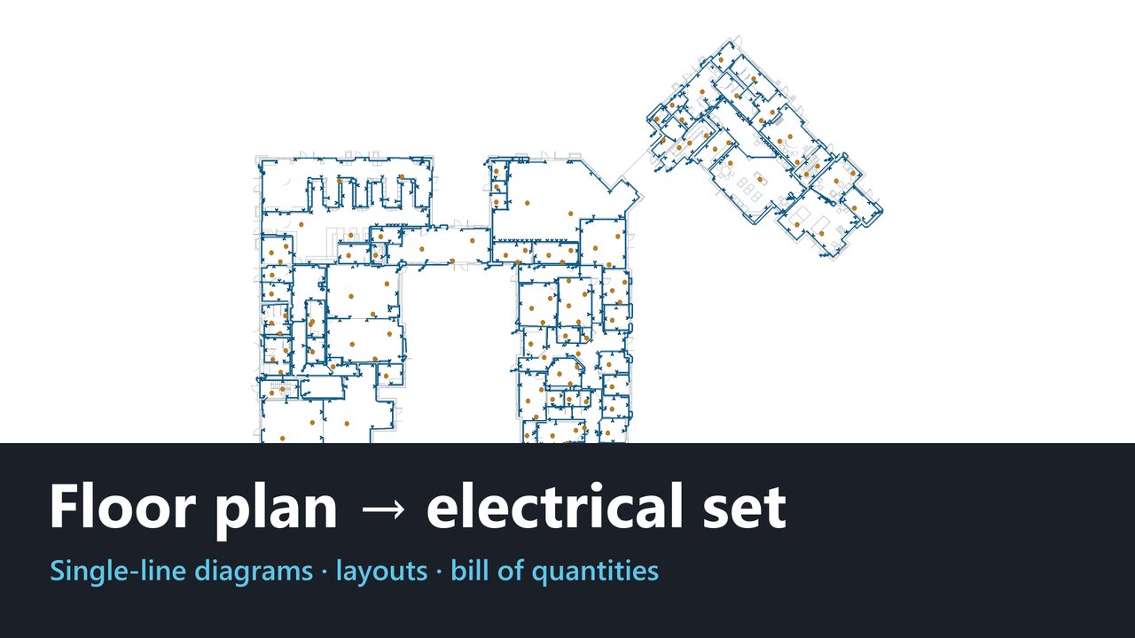
Press play: on the architect's base plan, we route the cables along the walls and place the sockets. This is one real floor from a project.
What the animation shows
This is a real floor of an apartment building, taken from the architect's floor plan as it arrived in DWG. The walls are the architect's own; nothing was redrawn.
Every cable follows the walls, the way it is actually installed, never diagonally across a room. That is why the cable lengths in the bill of quantities are measured along those routes, not estimated.
How many sockets and lights go into each room, and at what height, is the engineer's decision. From those decisions we draw the routes, the layouts, the single-line diagrams and the bill of quantities. The video below follows the same floor to the finished sheets.
The whole set in 49 seconds
The same floor, carried through to the finished sheets: the single-line diagram, the socket layout and a bill of quantities measured off the drawings.
The video loads from YouTube, in privacy-enhanced mode, only when you press play.
Need the whole set drawn?
Send us the architect's floor plan — we return the complete drawing set and the bill of quantities as editable, unstamped DWG. You review, stamp and sign under your own licence.