From the circuit list to the single-line diagram
First published in Italian: original on ElectroYou · The English version of this series is also published as articles on our LinkedIn page — follow on LinkedIn
The third article in the series. In the second part we decoded the architect's base drawing down to rooms and units; here we follow the same building from that point to the single-line diagram. This is the stretch where nothing gets drawn any more: the electrical diagrams are derived from the plans.
It's the same building as before: eleven storeys and thirty-eight apartments — six per floor on the six typical floors, two on the set-back top floor — plus a three-level garage, two commercial units, lifts and four electric-vehicle charging points.
1. Counted, not estimated
The maximum power available to each unit — the figure the limiter at the meter enforces — isn't a design decision. The network operator sets it in its connection conditions, in a table. Here that means thirty-eight apartments at 17.25 kW on a three-phase 25 A supply, two commercial units at 34.5 kW, one metering point for the landlord's services, three for the garages and four for EV charging, followed by the heating substation, the lift, the car lift and the booster pump set: fifty-two metering points in all, with 192.5 kW approved. These are the inputs, not the results.
What the design has to produce is everything behind each metering point: the circuits, their loads and the protective devices.
The method gets there by counting, and it counts according to a rule tied to the type of room: five sockets in the kitchen, three in the living room, two in each bedroom, two in the bathroom, one each in the hall, on the terrace and in the storeroom, and at least one lighting point per room. That isn't a standard. It's established practice written into a table, so that it applies to every room in exactly the same way.
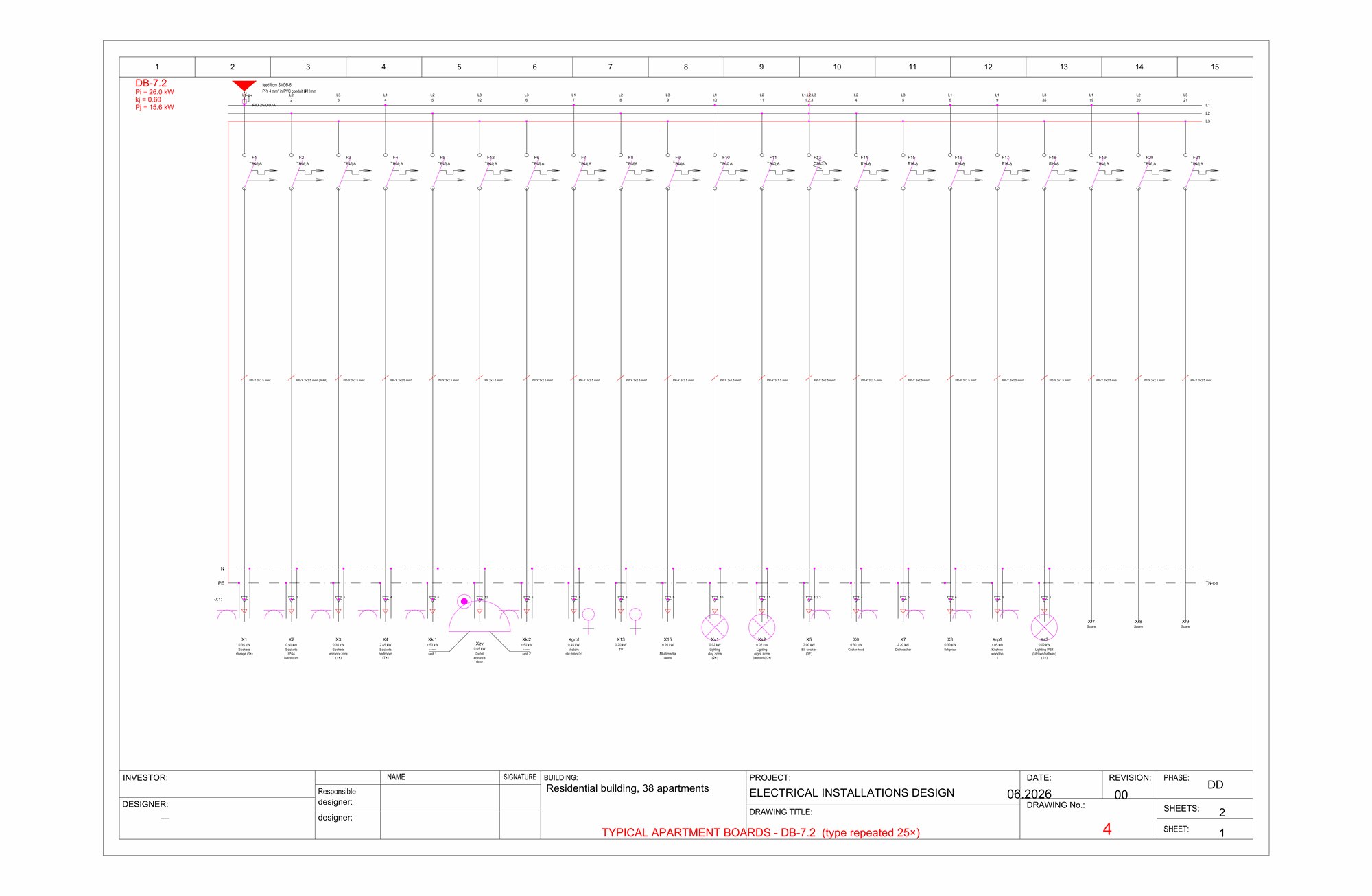
The socket and lighting layouts of this building show 1,110 sockets and fixed connections — hob, dishwasher, water heater, air conditioners — and 366 light fittings, with 196 one-way and 70 two-way switches. A typical floor has about a hundred and fifty of those points; the ground floor, with the two commercial units, has twenty-six. The count gives the installed load of each apartment, and applying the apartment's diversity factor gives its maximum demand, which has to stay below the contracted limit. A typical apartment in this building has 26 kW installed: a 7 kW hob, the water heater, dishwasher, fridge, cooker hood, two air conditioners, the roller shutters, and every socket and light in its rooms. Nobody switches everything on at once: with the diversity factor the method uses for an apartment, 0.6, demand comes to 15.6 kW, under the 17.25 kW at the meter. The gap between those two figures is exactly what the count is there to prove. The count doesn't replace the network operator's figure; it justifies it, and it decides how many circuits the apartment needs and what each one carries.
2. The tree
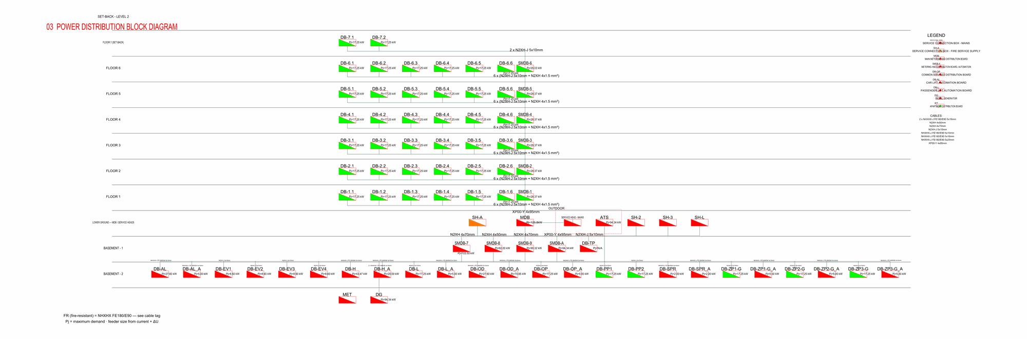
Once each unit's power is known, the rest of the distribution is a tree. The meters aren't in the apartments: the six meters on each floor, each with its limiter, sit in a shared board on the landing — the floor sub-main distribution board, or SMDB. From there a cable runs to each apartment's distribution board, the DB. The floor boards are fed from the main distribution board, the MDB, in the basement, where the supply from the substation comes in. The connection conditions for this building provide two such supplies: one for the thirty-eight apartments, the other for the commercial units, the EV charging, the garage and everything else. Next to the MDB stand the boards for the landlord's services, for the lifts and EV charging, and for the life-safety systems with the standby generator.
Power flows up the branches, and at every node it turns into a current and a cable size. Each apartment gets a 5×10 mm² cable for its 26 A. A floor board serves six apartments: not 6 × 17.25 = 103.5 kW, because six households don't switch everything on at the same time, but 28.4 kW — which calls for a 4×70 mm² cable and a 250 A main breaker. Five floors with six apartments each give the same figure five times over, because the rule is the same.
The cable size has to satisfy three conditions at once. It must carry the current without overheating. It must keep the voltage drop to the furthest load within the permitted limit — the worst case in this building is 1.66%, against a limit of 5% for lighting and 8% for everything else. And in the event of a fault, it must let enough current through for the protective device to trip in time.
The same tree then has to be placed on the floor plans: where each board goes, where each cable starts, which shaft it rises in. That's a drawing of its own, but it doesn't involve a single new decision. It's the tree seen in section.
3. The building's peak demand
The peak demand of the residential part isn't the sum of thirty-eight apartments. It needs a diversity factor at building level — the same principle as for the floor board, applied to all the apartments together.
How much that matters is clear from the limit the connection conditions set for the whole building: 192.5 kW. The maximum demands of the fifty-two metering points add up to 951 kW, so the approved figure is about a fifth of the total. Diversity isn't a refinement of the calculation; it's the constraint the building has to fit within. Without it, this building would ask for a supply five times bigger than it needs.
That factor doesn't come from a wiring standard. It's set by the network operator: the standard says how the installation must be built, while the network operator says how much power its network has to carry. Its method gives the coincident demand per customer as a function of the number of customers. Above twenty customers, peak demand grows with the number of customers raised to the power of 0.88, so the share per apartment goes down: with thirty-eight apartments it's 3.30 kW each, and thirty-eight times 3.30 is 125.3 kW. The input isn't the sum of the calculated loads; it's the number of customers. And it's thirty-eight because that's how the connection conditions group the apartments: one cable from the substation for the thirty-eight apartments, another for everything else.
That doesn't mean the number of appliances in an apartment is irrelevant. It doesn't go into the formula directly, but it comes in through the constraint: every apartment has to fit within its 17.25 kW. As long as it does, the building's peak depends only on how many apartments there are. If one doesn't, that apartment needs a bigger supply — 32 A instead of 25 A, or more — and the building's peak goes up with it. But the count gets checked first: an apartment that comes out at 58 kW is almost certainly a counting error, not reality. A bigger supply is the second step, and the connection conditions themselves provide for it. Only after that do the assumptions get trimmed: a smaller hob, a single water heater. What you don't do is note the limit and say nothing. That's why the count decides two things: how many circuits and what cable sizes the apartment needs, and whether the per-apartment limit holds. For everything that isn't an apartment — landlord's services, garage, EV charging — the power comes straight from the counted circuits anyway.
It's the same formula that gave 28.4 kW for the floor board, with six customers instead of thirty-eight. One rule, applied at every node of the tree. Add the little that the residential supply carries besides the apartments, and the main board of this building comes to 125.8 kW — the figure shown in its box in the diagram.
4. The diagram is derived, not drawn
By this stage, the single-line diagram isn't drawn. It's compiled.
There are thirty-four sheets, but nobody decides how many: the number follows from the list of boards. The thirty-eight apartments come down to a handful of types, and a single type covers twenty-five of them. Thirty-four sheets don't mean thirty-four separate drawings.
Nor are they drawn by hand. The whole chain is a program: a Python script reads the plan, counts the equipment, runs the calculations — loads, currents, cable sizes, voltage drop, fault current — and writes the sheets as DWG files that open in CAD, title block and legend included. The same program produces the bill of quantities. At no point in the chain does anyone open CAD and draw: you run it, and the sheets come out.
Inside each board, the circuits follow declared rules: one socket circuit and one lighting circuit per room, no more than eight sockets per circuit (four in the kitchen), and no more than ten lighting points. The kitchen gets six circuits for its fixed appliances — hob, cooker hood, dishwasher, fridge, water heater and a spare — plus four more for the worktops. The bathroom is a group of its own, with two circuits per bathroom behind the RCD the standard requires. The air conditioners and roller shutters have their own circuits, and two ways are left free for whatever the occupants add later. The main breaker at the head of each board, and the size of the cable feeding it, come from the tree described above. That's why the single-line diagram comes last: it needs both the circuits from the count and the supply from the distribution layout. Nothing is copied from one sheet to another, because nothing is copied from the previous project.
There's one exception, and it's only fair to mention it. Standard installation details — how cable labels are fixed, crossings with other services, penetrations through a fire wall — are identical from one building to the next, and copying them is the right thing to do. It's the only place where it is.
In the next part we go back to the first block. In the second part we read the base drawing; here we took it for granted that the equipment was already on the plan. It wasn't: someone decided where each of those 1,110 sockets goes, and the standard doesn't make that decision for you. This is the part of the work where the furniture, the walls and the habits of the people who will live there come into play.