Where the sockets go (and the lights)
First published in Italian: original on ElectroYou · The English version of this series is also published as articles on our LinkedIn page — follow on LinkedIn
The fourth article in the series. In the third part the sockets and lights were already on the plan, and we derived the circuits, the boards and the diagram from there. Here we take a step back: how do you decide where each socket and each light goes? It's the only step in the whole job where a real decision gets made. Everything else is calculated.
1. The rule sets the minimum, not the position
We start from a simple rule based on room type: five sockets in the kitchen, three in the living room, two in each bedroom, two in the bathroom, one each in the hall, the storeroom and on the balcony, and a ceiling light in every room. It's the same table that gave the number of circuits in the third part, and nothing goes below that minimum. In some countries the standard also sets a minimum per room — in Italy, for instance, in three levels — and where it does, that minimum comes first. We don't sign designs in the countries where these buildings are built: we apply the rule and the network operator's connection conditions, and the check and the signature stay with the engineer in charge.
But the rule says how many sockets, not where they go. "Two sockets in a bedroom" holds for a nine-square-metre bedroom and an eighteen-square-metre one alike, whether the bed is against the short wall or the long one. The number is settled; the position isn't. And the position is what the occupants will live with for thirty years.
2. The walls say where a socket can go; the furniture says where it's needed
The first filter is the walls. A socket goes on a wall: not on a window, not on a door, not on a thirty-centimetre stub of wall, not in the part of the bathroom that water can reach. From the plan we read in the second part, we know where every room's walls and openings are. So we know where a socket can go — but not yet where it's needed.
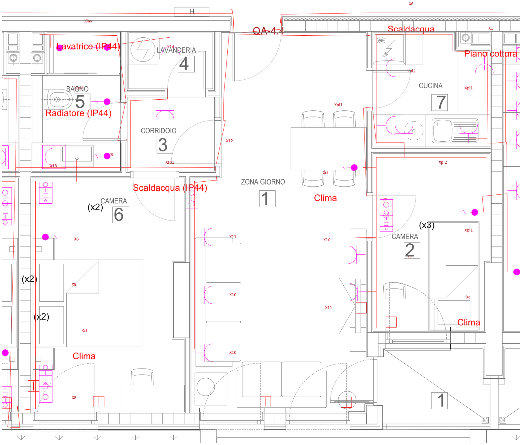
The second filter is the furniture the architect drew. It never appears on the electrical drawing, yet it decides everything. The bed wants two sockets, one on each side, at bedside-table height. The dining table wants one on the nearest wall. The TV wall wants a group. In the kitchen, the worktop wants a row of sockets above it, and every built-in appliance — hob, oven, dishwasher, fridge, cooker hood — wants its own connection behind it. (A fixed connection is a point where an appliance is wired in directly, with no plug.) The bathroom is different: it has few sockets, and fixed connections take their place — water heater, washing machine, extractor fan, heater — each one where the appliance stands.
Put the two filters together and every socket has a reason you can see on the plan: this one is here because of the bedside table; that one because the worktop ends here; that connection because the water heater is right behind it. That's the socket layout in the figure, for a typical apartment in this building. The walls and the furniture are the architect's; the sockets and connections follow from them. Every symbol carries its circuit code — the same code that appears on the board in the third part.
3. Everyday habits decide the switches
For lighting, the rule is simpler: at least one ceiling light per room, with the protection the room calls for — standard fittings in the bedrooms, protected fittings in the bathroom, on the balcony and in the basement. This building has 366 of them.
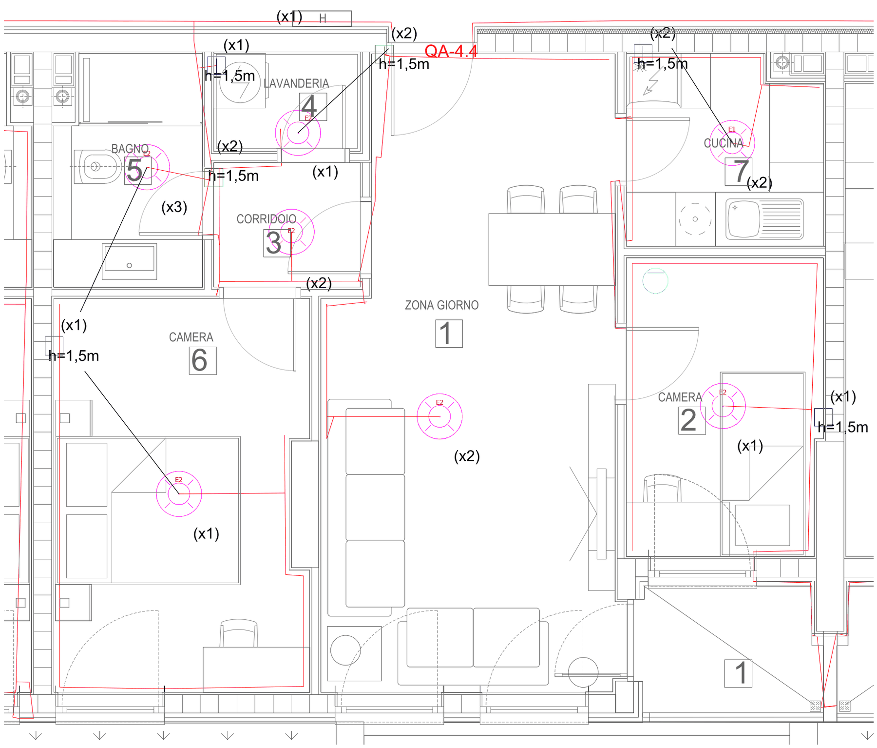
It's the switches that call for decisions. A switch goes at the entrance to the room, on the handle side, so your hand finds it before the door is fully open. A long corridor is switched from both ends, with a two-way switch at each end — two-way switches let you turn the same light on and off from two places. The same goes for a staircase, or a bedroom where you want to switch the light off from bed. This building has 194 one-way and 72 two-way switches. How many two-way switches you need isn't written in any standard; it depends on how people move around their home. That's furniture too, in a broader sense: not the pieces, but the routes between them.
Here is the lighting layout of the same apartment: one light per room, the switch by the door on the handle side, and a two-way switch wherever a room has two entrances.
4. Cables follow the walls
Once the sockets and lights are in place, one cable per circuit leaves the apartment board near the entrance. The cable doesn't take the shortest route; it takes the shortest route along the walls. It runs in the wall under the plaster, or in the ceiling for the lights. It turns where the wall turns. It passes from one room to the next above the door, never diagonally across a room. In the bathroom, it keeps to the same zones as the sockets. Each circuit has a main run along the wall, with short spurs to the individual sockets. That means one chase per wall, and every socket reached with the least possible cable.
On the plan, the cable is drawn where it will actually run: it's the red line along the walls in both figures. That matters because the length of every run is measured, not estimated, and that length is used twice — to check the voltage drop from the third part, and to give the cable quantity in the bill of quantities, in the fifth part. In the typical apartment shown in the figures, the cables run about 45 metres for the sockets and 47 for the lighting. Across the whole building, that's 3,235 and 2,978 metres.
5. The count, room type by room type
With all three filters applied — minimum, walls, furniture — the count for the thirty-eight apartments comes out like this. The minimum in the table gives 564 sockets and 250 lights. The actual layout gives 773 sockets and 359 fixed connections, 1,132 points in all, plus 276 lights. The difference shows up room by room.
Living rooms: minimum 117; 319 sockets and connections placed, almost three times as many. The TV, the table and, in fifteen apartments, a kitchen open to the living room with its worktop.
Bedrooms: minimum 162; 323 placed. Both sides of the bed, the desk, the air conditioner.
Kitchens, where the kitchen is a separate room: minimum 115; 140 placed. The row above the worktop, plus the built-in appliances.
Bathrooms: minimum 120 sockets; 70 placed — but with 233 fixed connections: water heater, washing machine, extractor fan, heater. The rule counts sockets; the layout turns them into connections. The figure that matters is the number of points: 303.
Halls, storerooms and wardrobes stay at the minimum: one socket each.
The minimum tells you the fewest sockets you can get away with. The furniture tells you how many you actually need. The gap between 564 and 1,132 isn't generosity; it's the furnished plan, read room by room.
6. The only step where a decision is made
It's worth saying plainly. In the whole chain — floor plan, circuit list, board diagrams, placement and cable routing, bill of quantities — this is the only block where a decision is made that doesn't follow from another block. The number of circuits comes from the count. The cable size comes from the load. The bill of quantities comes from the drawing. Placement doesn't come from anything upstream: it comes from the furniture, and the furniture is the choice of whoever designs the home.
That's why the check here is a reading of the furnished plan, room by room. Is the bed really here? Is this the worktop? Does every socket have its reason right next to it? The engineer in charge carries out that check. We set up the sheet so that it can be done at a glance: the furniture stays visible under the sockets, and every socket carries its circuit code.
The next part is the last, and it's about the bill of quantities: the count from this part turns into quantities and descriptions. And a bill of quantities derived from the drawing turns out not to be extra work at all — it's a question put to the model.