From the floor plan to the bill of quantities: a method for a complete set of electrical drawings
First published in Italian: original on ElectroYou · The English version of this series is also published as articles on our LinkedIn page — follow on LinkedIn
If you design electrical installations for housing, you probably spend more time cleaning up drawings than deciding anything about the installation. This article isn't about regulations. It's about method: how a complete set of electrical drawings, together with the bill of quantities, can be derived from the architect's floor plan so that no two drawings ever contradict each other.
First, a word about who we are. We don't sign designs in the countries where these buildings are built. We have more than twenty-five years of experience in electrical engineering, and we produce drawings for design offices: we apply the local rules in the drawings, and the check and the signature stay with the engineer in charge. That's why this text doesn't explain regulations — that belongs to the people who sign under them. It's about how the drawings are made.
1. Everything depends on the base drawing
The architect's DWG isn't just an attachment. It's the data structure that all the later work sits on, so before the first lighting point goes on the plan, five things are worth checking.
Closed rooms. Each room should be bounded by a closed polyline, or at least by walls that actually meet. If the outline is open by as little as two centimetres, no procedure can tell for sure which room a socket next to the door belongs to. From then on every assignment is manual, and every revision means doing it all again.
Layers by function. Walls, doors and windows, furniture, dimensions, hatching and text each belong on their own layers. If the furniture sits on the wall layer, you can't turn it off to read the plan, and every sheet starts out cluttered.
Room names and areas as real text. "Living room 24.60 m²" has to be a text object on a layer you can identify. Those labels feed the legend, the room schedules and half the descriptions in the bill of quantities.
Consistent units and scale. If a file was saved in different units from the ones it claims to use, blocks come in scaled up or down by a factor of 1,000.
No stray geometry. A forgotten line a few kilometres from the building throws off the drawing extents, and with them every view that is generated automatically.
So what does a "clean" base drawing actually mean? One received recently had 224 layers, and it wasn't messy. None of them was empty; each one meant something to whoever drew the plan. The problem isn't junk to throw away, it's sheer volume. The electrical work needs about ten of those layers — walls, openings, room names and areas, dimensions — and everything else has to switch off in one go without taking those ten with it. If the layers aren't separated by function, that can't be done, and you end up working on a cluttered plan the whole time. Half a day spent understanding and cleaning up the base costs less than a single revision on sheets that are already laid out.
2. Read the building before you draw
Before placing a single symbol, read the building: how many rooms there are, what each one is for, what belongs to each apartment and what serves the building as a whole. That split decides how many distribution boards you need, how many risers, and where the main cables run. Leave it for later and you'll run into it halfway through the drawings — and then you redraw.
In a multi-storey building, look at what happens vertically as well: where the shafts go, and whether the plant rooms line up from one floor to the next. A riser that runs into a beam on the third floor is a design problem, not a drafting detail.
The layout follows what a room is used for, not how long its walls are. Six metres of living-room wall and six metres of corridor don't need the same thing.
3. Sockets and lights: follow the furniture and the way people move
Sockets go where the furniture will be, not at regular intervals along the wall. In the kitchen, what matters is the worktop and the built-in appliances; in the bedroom, both sides of the bed; in the living room, the TV wall.
Switches follow the way people move through the home: one at the entrance to each room, on the handle side of the door; two-way switches at both ends of a long corridor or a staircase; an intermediate switch once there are three places to switch from. These are design decisions, not something to settle on site. Leave them to the installers, and the drawings and the installation part ways on day one.
Bathrooms, outdoor areas and other wet locations are where placement stops being a matter of convenience. Clearances, equipment ratings and protective measures there follow the local rules, and the engineer who signs checks them again every time the architectural base changes.
4. Circuits and numbering: the backbone
This is where you find out whether the work will survive revisions. Every point carries the identifier of its circuit, and that identifier has a fixed structure: board, apartment, circuit type, sequence number. Which convention you pick doesn't matter. What matters is having one and never straying from it.
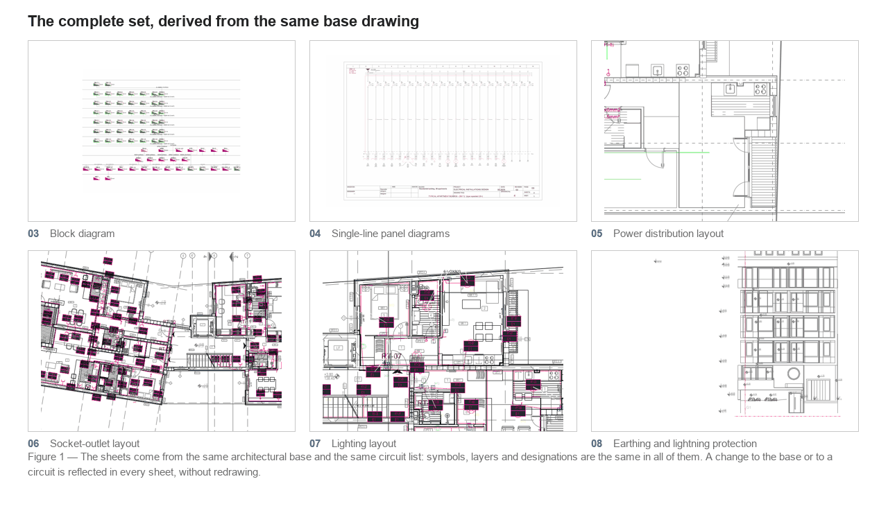
With consistent numbering, the board's single-line diagram is no longer a drawing in its own right; it follows from the plan. There is one circuit list, taken from the plan, and the diagram is generated from it. Never two lists: two lists always drift apart, and they do it quietly.
The classic mistake is the reverse: a single-line diagram drawn on its own and updated "when there's time". It falls behind, and the installer is the one who finds the difference, on site.
5. The bill of quantities is a query, not a count
If every symbol carries its own item — code, description, unit — the bill of quantities comes from counting symbols and adding up lengths by type. It isn't a separate job to do at the end. It's a question you ask the drawing, and it's the only way to keep the bill in step with the sheets after the third revision.
Whatever the drawing doesn't contain stays with the designer: wastage, drops and vertical runs, builder's work, sundries, prices and, above all, the sanity check. If the number of points doesn't fit the number of rooms and what they're used for, the mistake is upstream, in the model — not in the spreadsheet.
6. What the method does, and what it doesn't
The method takes care of consequences. Anything that follows from a decision already made — geometry, counts, consistency between sheets, a change rippling through the whole set, the legend, the title blocks — can be generated instead of copied, and it should be, because copying is the surest way to end up with two sheets that disagree about the same thing. The tools aren't exotic: block attributes to carry data inside the symbol, data extraction to tables for lists and the bill of quantities, references and fields so the title block fills itself in. Every CAD package has had them for twenty years. What's usually missing isn't the tool but the discipline to use it consistently from start to finish.
The method doesn't make decisions. Sizing the cables, coordinating the protective devices, deciding what the building needs beyond the minimum, judging the special cases: none of that follows from the plan. It comes before it. No drafting discipline produces those decisions or replaces them; at best, it shows sooner that they're missing.
The method has limits of its own, and they're worth spelling out. It's only as good as the base drawing: on a messy file, it produces order that isn't real. It's only as good as the naming convention: change the structure of the identifiers halfway through and everything gained so far is lost. Above all, consistency isn't correctness. A perfectly consistent set of drawings can be consistently wrong, and the consistency makes it all the more convincing, because an error spreads just as efficiently as a correction. The real check is still done by a person, and it has to be someone qualified to do it.
A design is signed by a person. Compliance with good engineering practice and with the requirements where the building goes up is the responsibility of the engineer who signs, and it can't be handed over to a method or a procedure. No tool signs a design.
7. A note on languages
Sooner or later someone asks for the same set of drawings in more than one language. It's a good test of an approach that pays off even if you only ever work in one: text shouldn't live in the drawing, it should live in the model. If legends, title blocks and item descriptions are attributes of objects rather than text placed on the plan, then the drawings, the room schedules and the bill of quantities all become views of the same information. You correct something once, and the correction shows up everywhere. If the text is scattered across the sheets instead, every revision turns into a treasure hunt, whatever the language.
This has limits too, and they should be stated plainly. Translated technical descriptions need to be checked by someone who knows the trade in the target language. And references to standards aren't translated at all: they're replaced by the standards of the country where the building goes up, and the engineer who signs there confirms the choice. A standard reference translated word for word points, at best, to nothing.
None of these rules is new. Whether a design survives its revisions or falls apart almost always comes down to two things: the quality of the base drawing and the discipline of the circuit numbering. The time the method saves goes where it's really needed — into the technical decisions, which no one can make on behalf of the person who signs.